Early ICU Ventilators
An overview of the early generations of ICU ventilators from the 1950s – 1979.


1950s
The early positive pressure mechanical ventilators are featured. The early vents were labeled as "respirators".
1954 Mueller-Morch Piston Respirator
Dr. Ernst Tier Morch, a Danish physician, developed a piston respirator during WWII in Denmark. After he relocated to the USA following WWII, he continued work on his ventilator designs. V. Mueller Company of Chicago began manufacture of the Morch respirator in 1954. The unit was designed to fit under a hospital bed. The unit was introduced when the polio epidemic in the United States was still at its peak and provided an alternative to iron lungs.
The ventilator provided a constant stroke volume up to 3600 mL directly to an uncuffed tracheostomy tube. It was the first ventilator to incorporate a humidifier
The ventilator provided a constant stroke volume up to 3600 mL directly to an uncuffed tracheostomy tube. It was the first ventilator to incorporate a humidifier
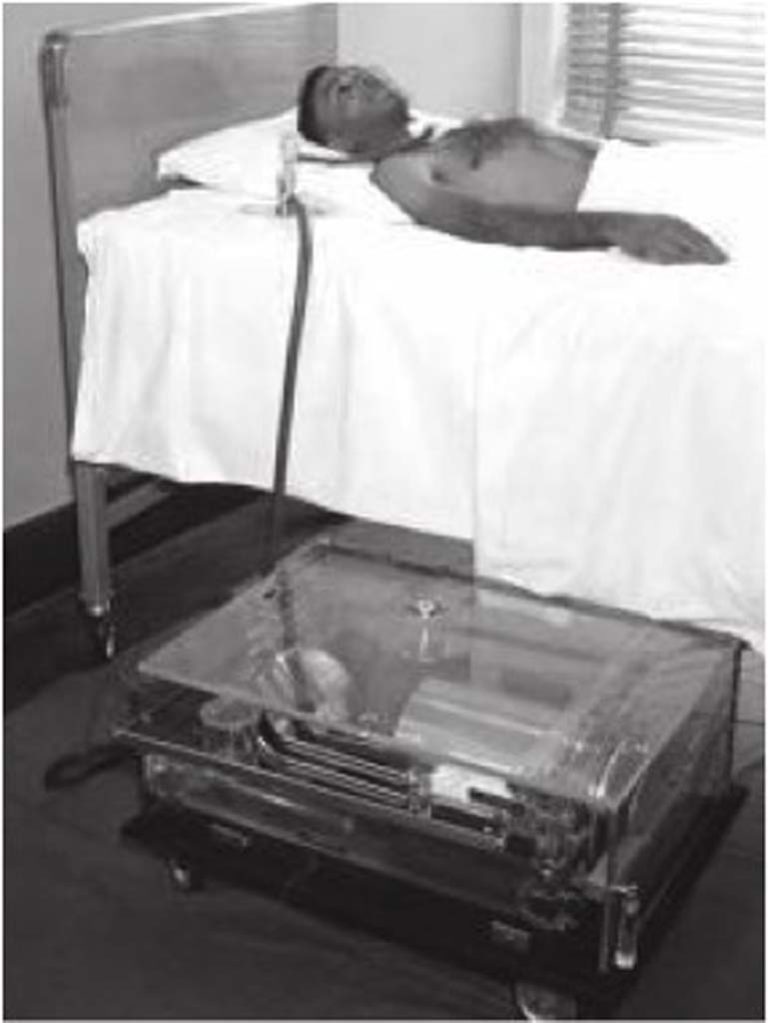
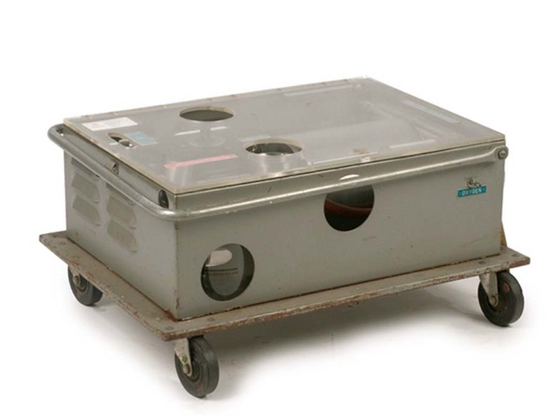
Mueller-Morch Respirator
The Mueller-Morch respirator was designed to fit under the patient's bed and was designed to attach via an uncuffed trach tube.
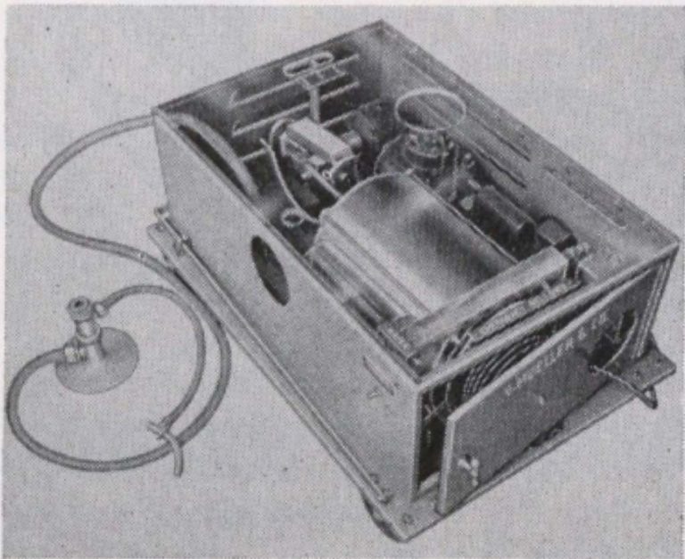
Mueller-Morch Respirator
This image of a Mueller-Morch Piston Respirator appeared in the "Equipment News" section of a 1959 issue of the INHALATION THERAPY journal. The respirator was described as "an intermittent positive pressure respirator for tracheotomy cases requiring artificial respiration." The unit provided "a constant stroke volume from 0-3600 mL and pumped room air or oxygen mixture through a humidifier to the tracheostomy tube, with a specially designed check-valve in the system near the tracheostomy tube to ensure exhalation as soon as the desired stroke volume has been delivered to the lungs."
The respirator was recommended for use with uncuffed trach tubes.
The respirator was recommended for use with uncuffed trach tubes.
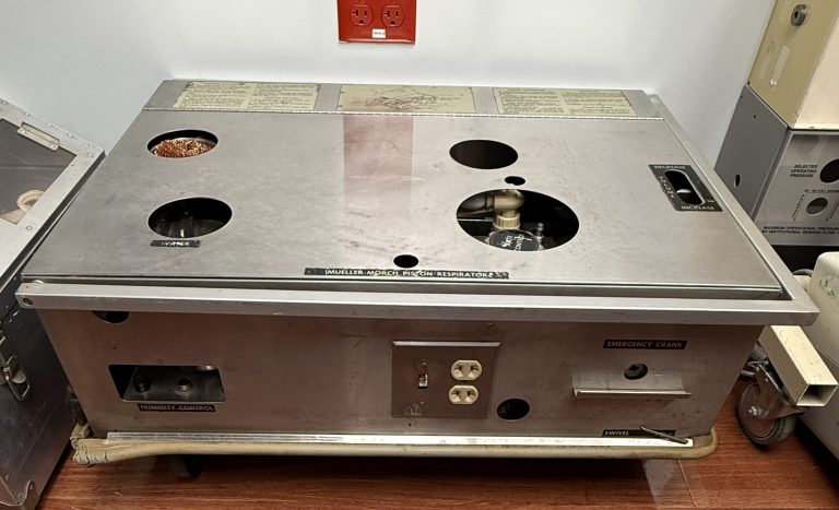
Mueller-Morch Piston Respirator
One of the remaining Mueller-Morch respirators in existence was recently donated to Felix Khusid's collection by John Weisleader.
Image from Felix Khusid
Mueller-Morch Piston Respirator
The internal components of the Mueller-Morch respirator are shown.
Image from Felix Khusid
NightLight
The Mueller-Morch respirator had a little built-in nightlight that could be switched on so staff could monitor the equipment more easily in darkened rooms.
Image from Felix Khusid
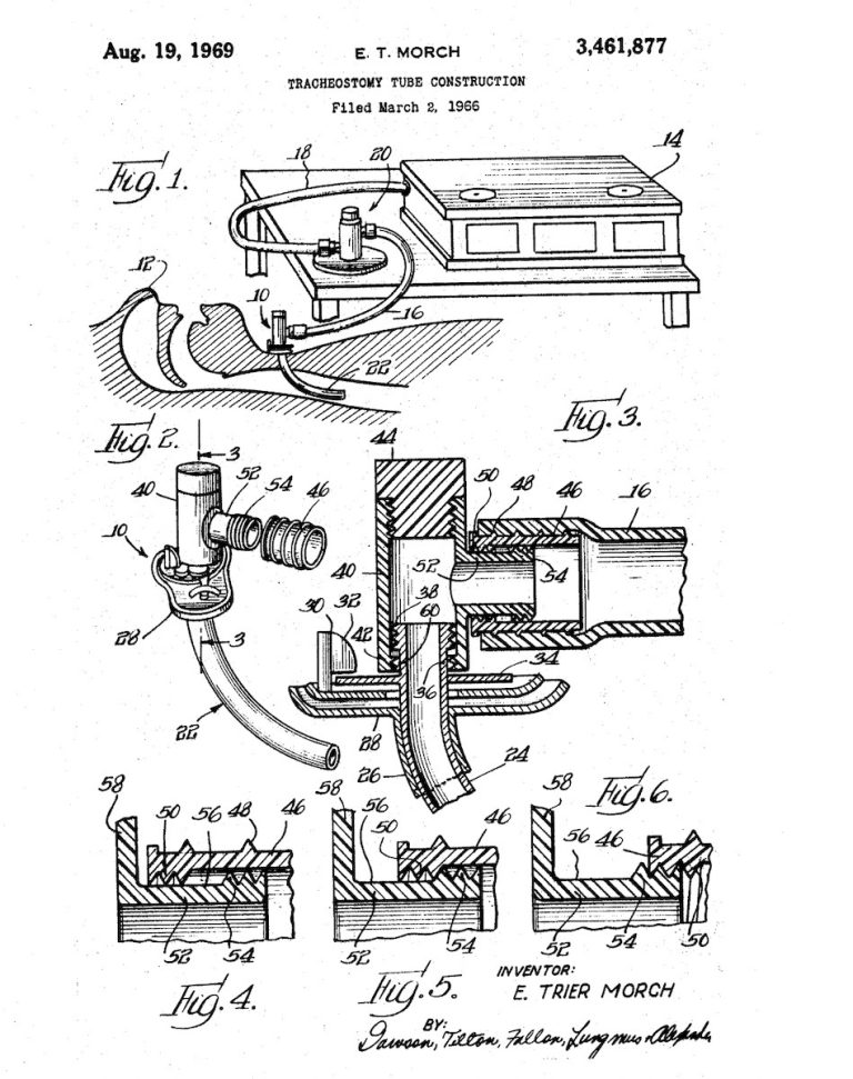
Morch Ventilator - Trach Connection
A patent application was filed in 1966 for the Morch ventilator connection that screwed directly onto the patient's trach tube. The patient was granted in August 1969.
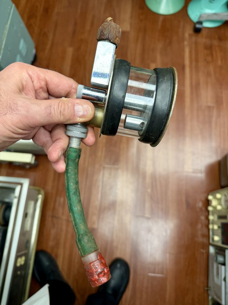
Morch Connector
The Morch patient connection is shown.
John Weislander donated this to Felix Khusid's vintage ventilator collection in 2024.
Image from Felix Khusid
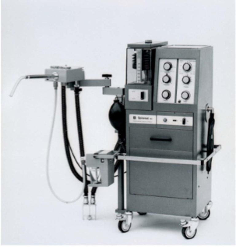

1955 Draeger Spiromat
The Spiromat ventilator was introduced by Draeger in 1955.
Image provided by Simone Burow at Draeger
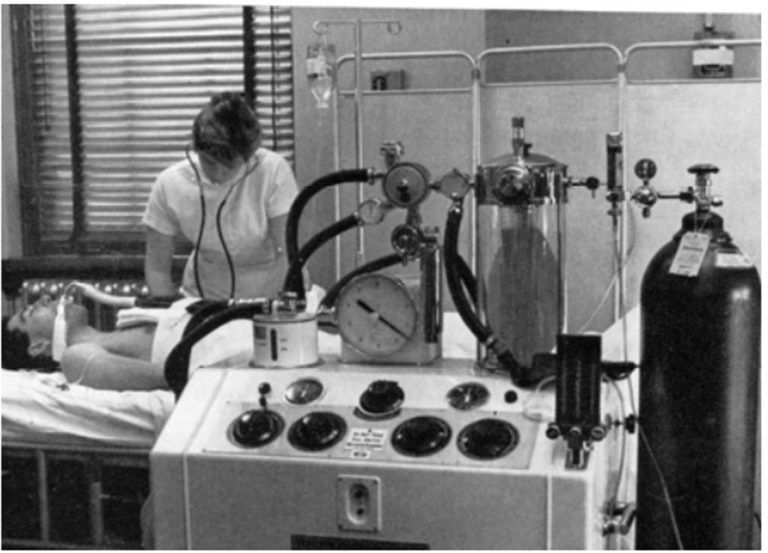
Engstrom Respirator
In the early 1950s, the Engstrom Post-Op respirator was developed by Carl Gunnar Engstrom. The respirator could provide volume controlled ventilation to adults and pediatric patients.


1960s
First generation respirators/ventilators are featured.
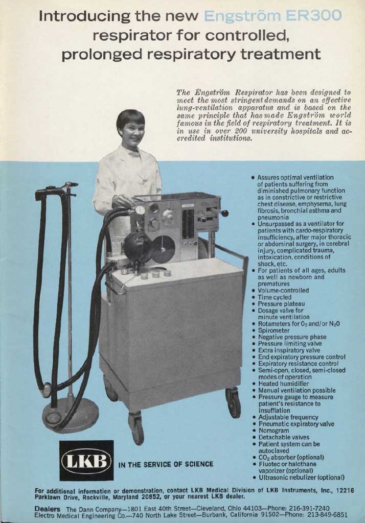
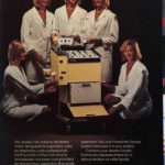
Engstrom ER300
This ad for the Engstrom ER 300 appeared in the August 1969 issue of INHALATION THERAPY.
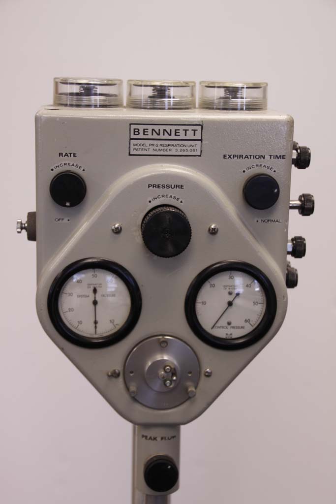
Bennett PR-2
The Bennett PR-2 was used often used to continuously ventilate patients in early ICUs.
Image from Illinois Central College Archives 1999
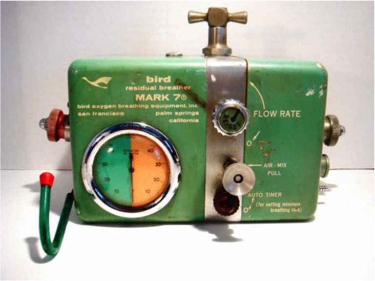
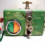
Bird Mark 7
The Bird ventilators, such as the Bird Mark 7 pictured here, were used to provide continuous ventilatory support to patients in the ICU.
Image from Dennis Glover
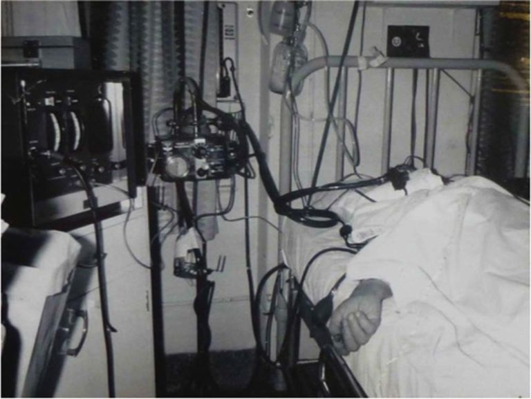
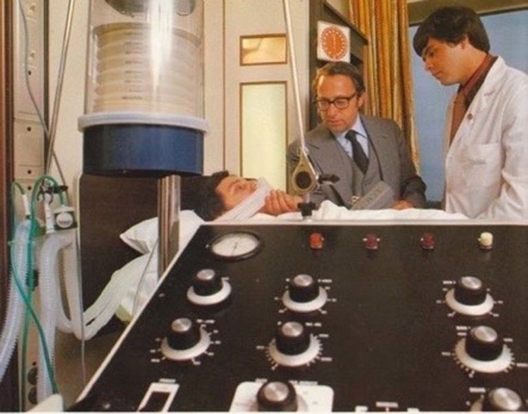
1960s Bird Mark 7 in ICU
This photo from the 1960s was taken of a patient being ventilated with the Bird Mark 7 respirator.
Image from Louis Phillip Bell-Isle
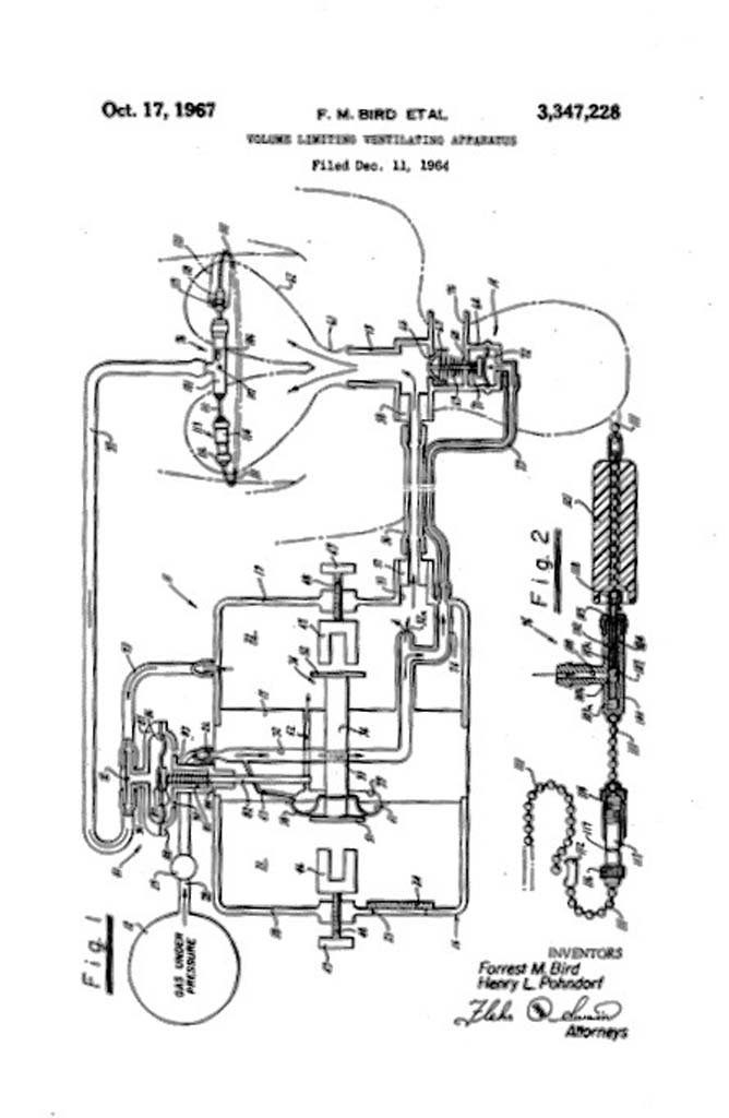
1967 Bird's Vent Patent
On December 11, 1964, Forrest Bird and Harry Pohndorf filed a patent application for "Volume Limiting Ventilation Apparatus". The patent was awarded on October 17, 1967.
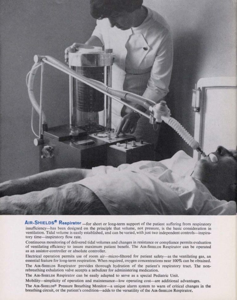
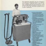
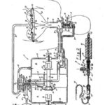
The Air-Shields Respirator
The Air-Shields Respirator is featured in this 1966 ad from the INHALATION THERAPY journal.
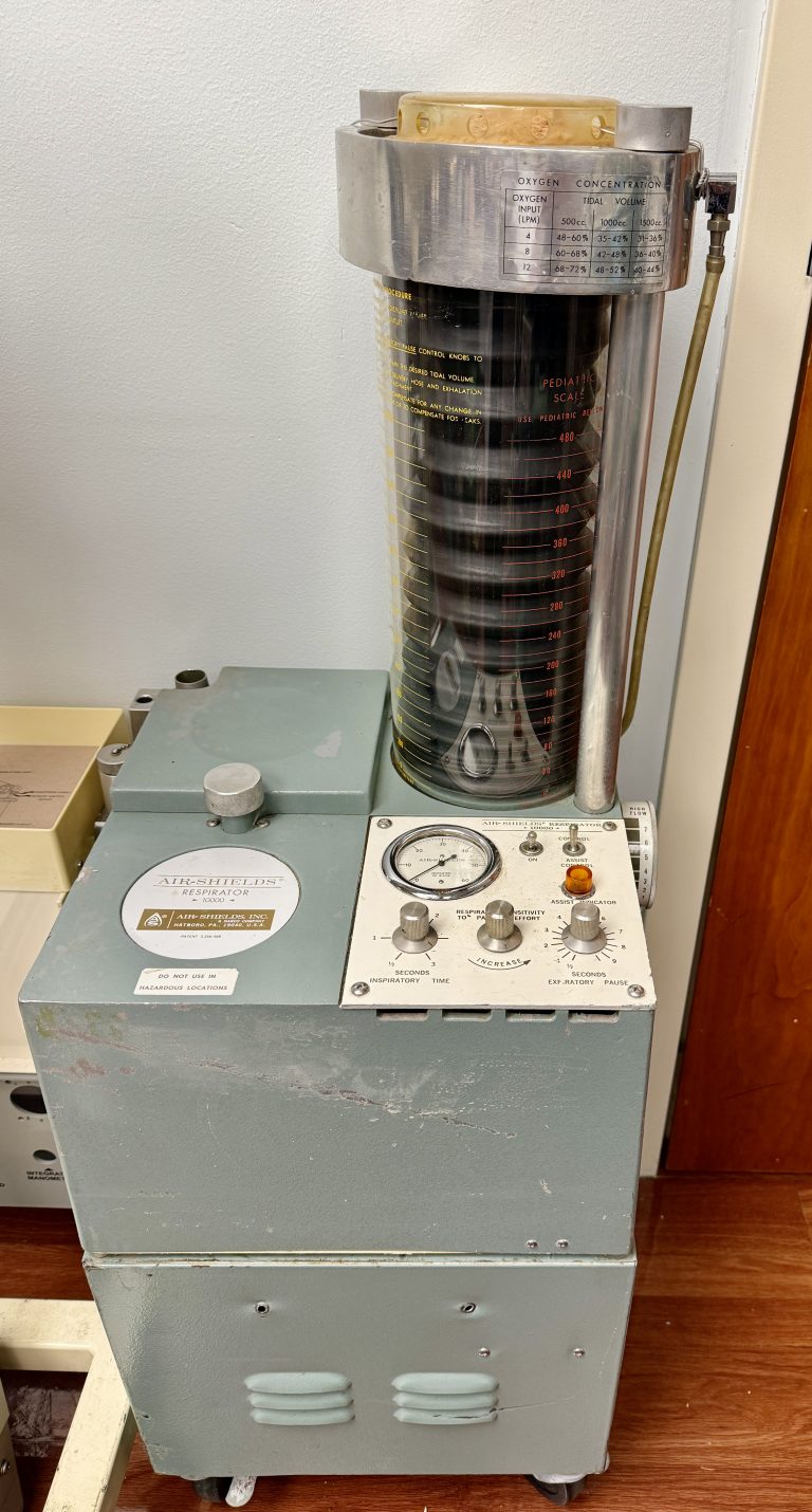
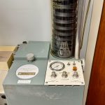
Air-Shields Respirator
This Air-Shields was recently donated to Felix Khusid's collection by John Weisleader.
Image from Felix Khusid
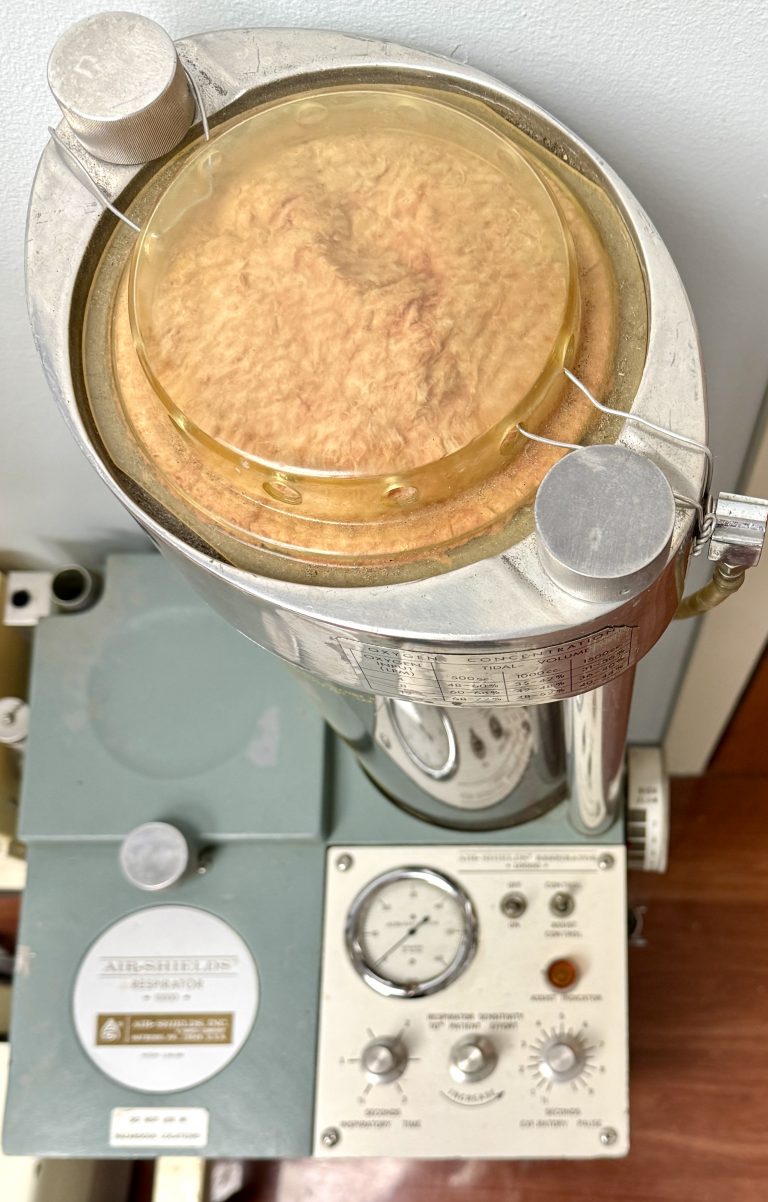
Air-Shields Respirator
View from top of a Air-Shields. The pink material is the filter on top of the bellows.
Image from Felix Khusid
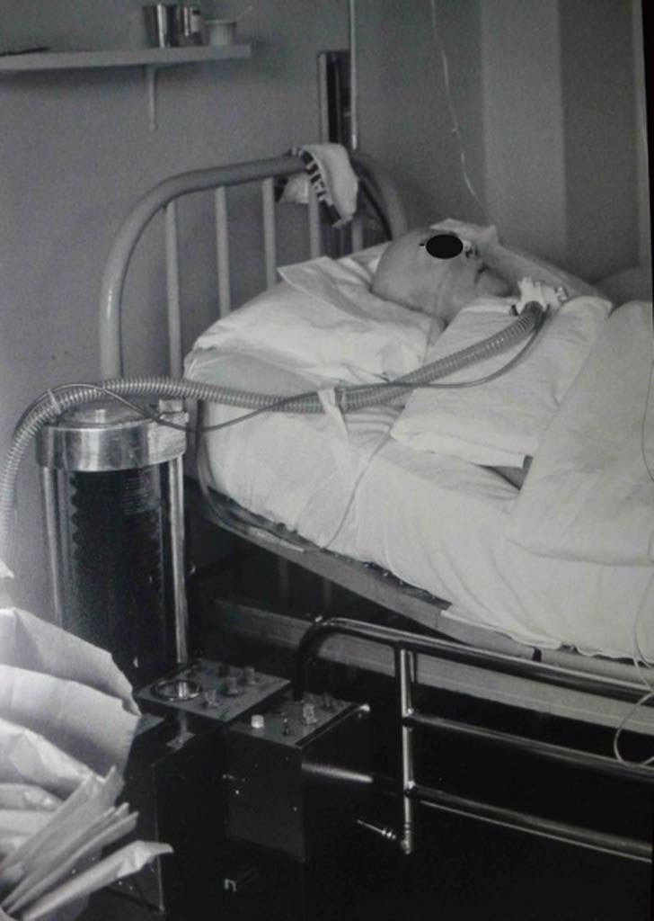
Air-Shields Ventilator in ICU
This 1960s photos shows an Air-Shields vent in use in ICU.
Image from Louis Phillip Belle-Isle
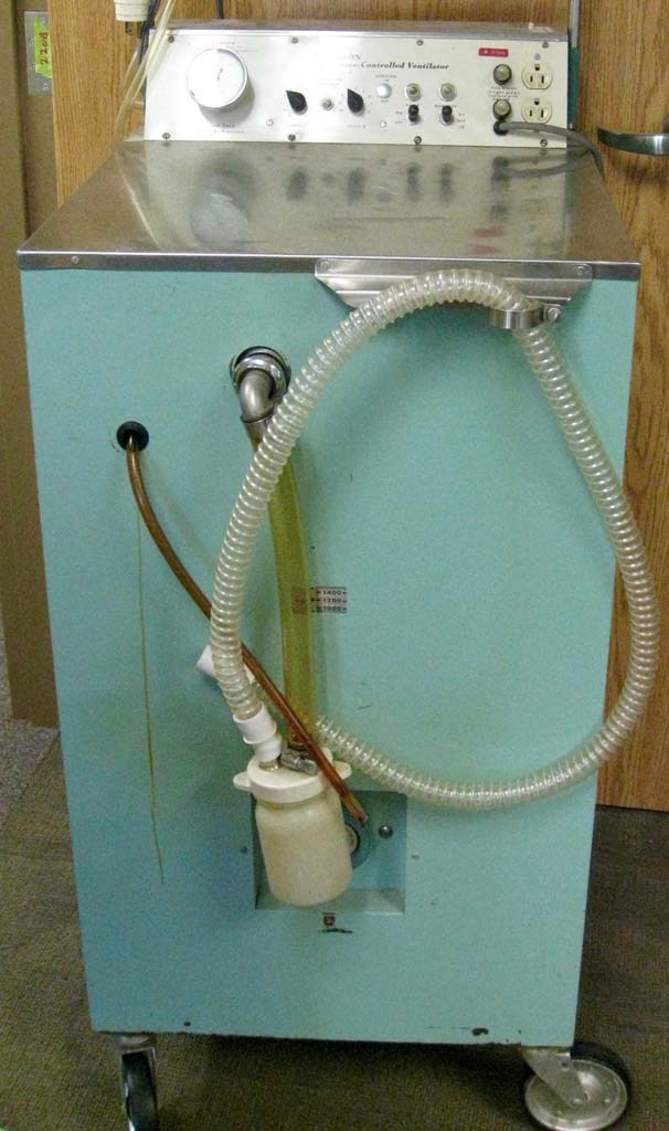
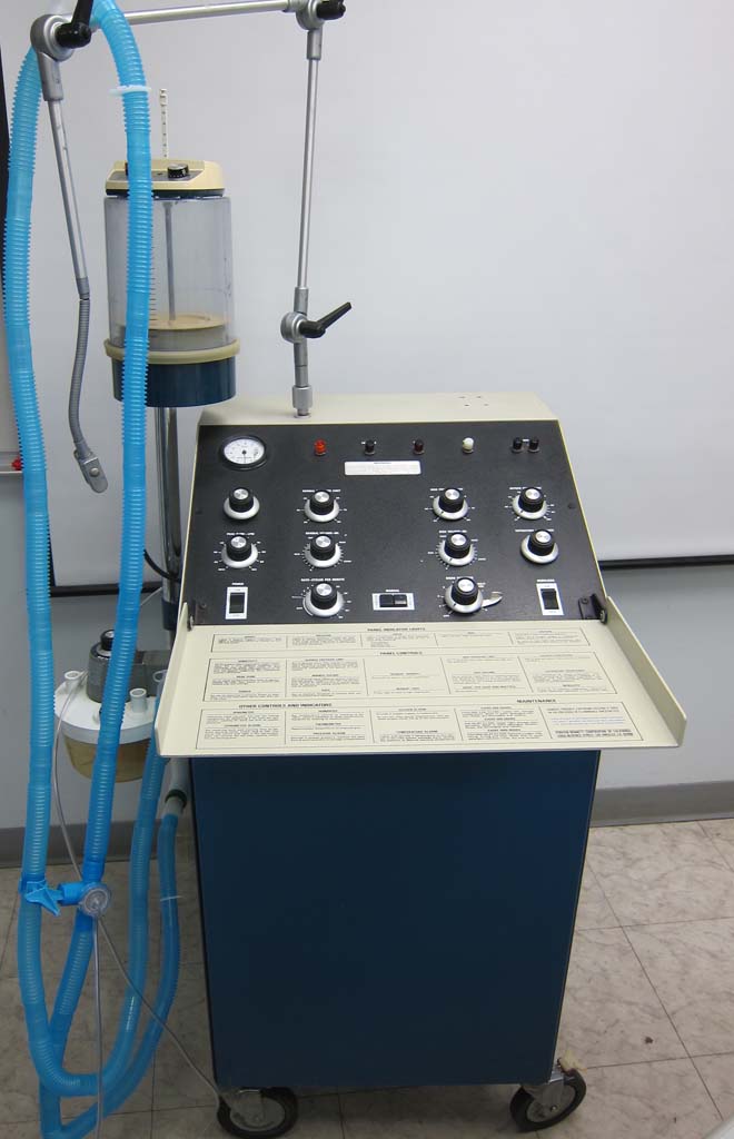
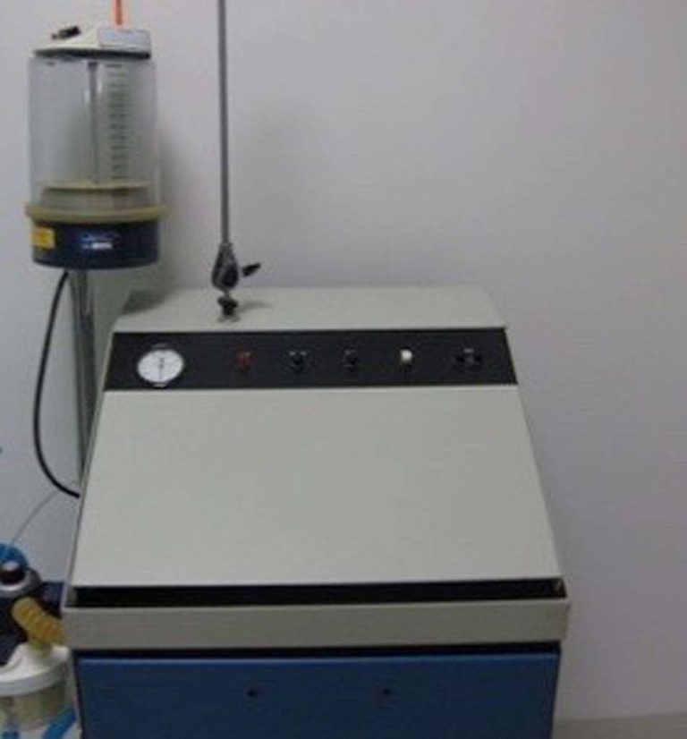
1964 Emerson 3PV
The Emerson 3PV respirator was introduced in 1964. J. H. "Jack" Emerson utilized a variety of components from his machine shop along with standard household items to create his ventilator.
Image from Charles Cornfield
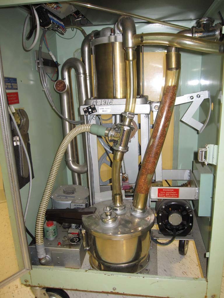
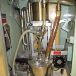
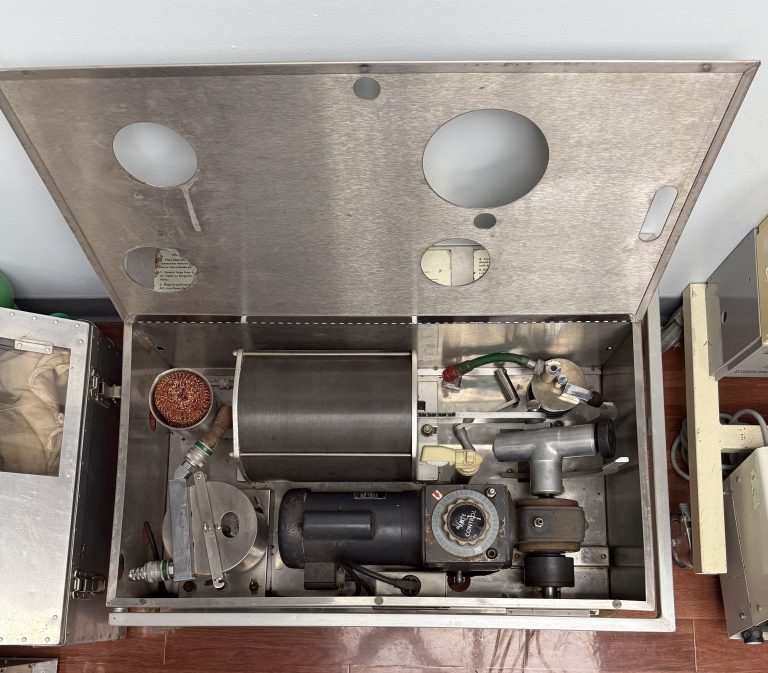
Inside the Emerson 3PV
When the left-hand side panel door to the Emerson cabinet opened, the hot plate, pressure cooker, copper mesh, trombone tubing, and wrenches are visible. The sigh mechanism utilized a vacuum cleaner motor. The cabinet itself was the housing for a washing machine.
Image from Joseph Goss
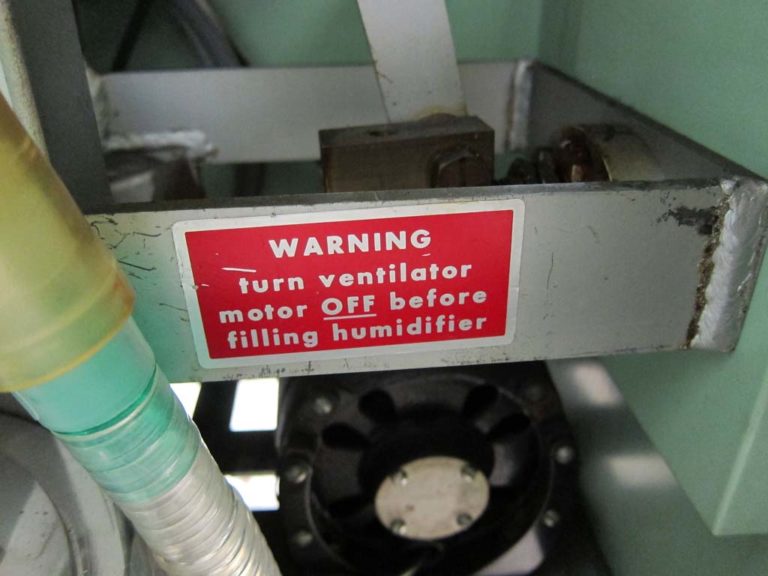
Emerson 3PV Warning
The permanent warning label inside the Emerson 3PV is shown.
Image from Felix Khusid
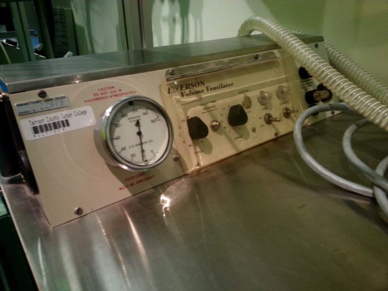
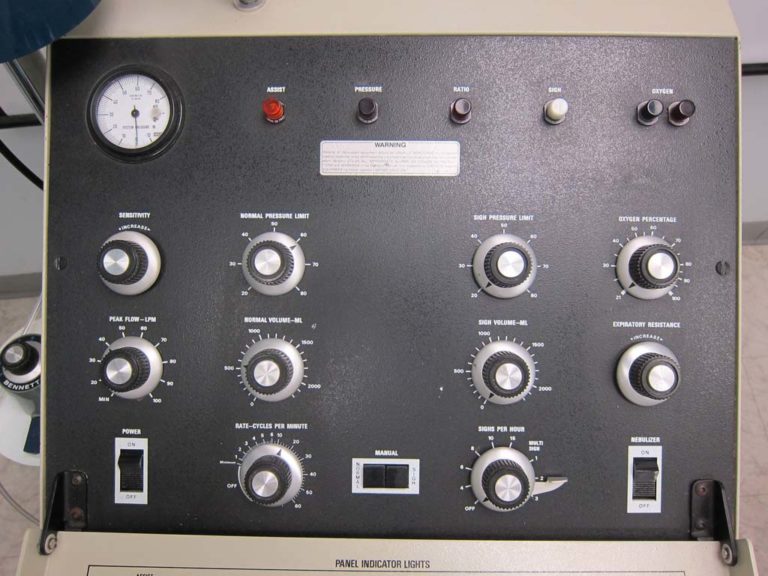
Emerson Control Panel
The control panel of the Emerson 3PV is shown.
Image from Jim Ciolek
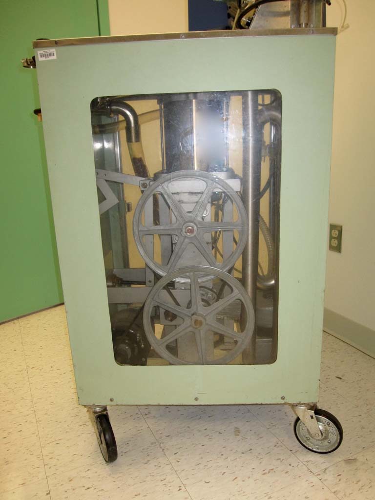
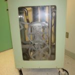
Right View of Emerson 3PV
The right side panel of the Emerson cabinet has been cut-away to reveal the internal components.
Image from Joseph Goss
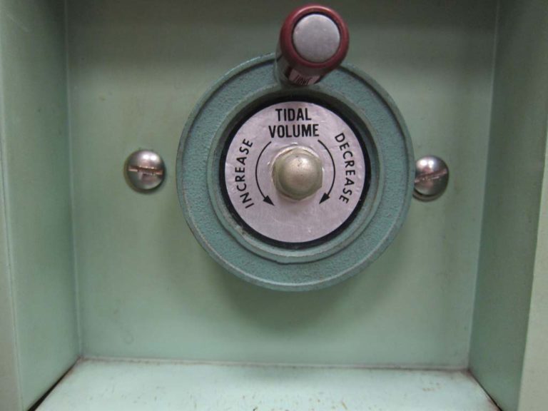
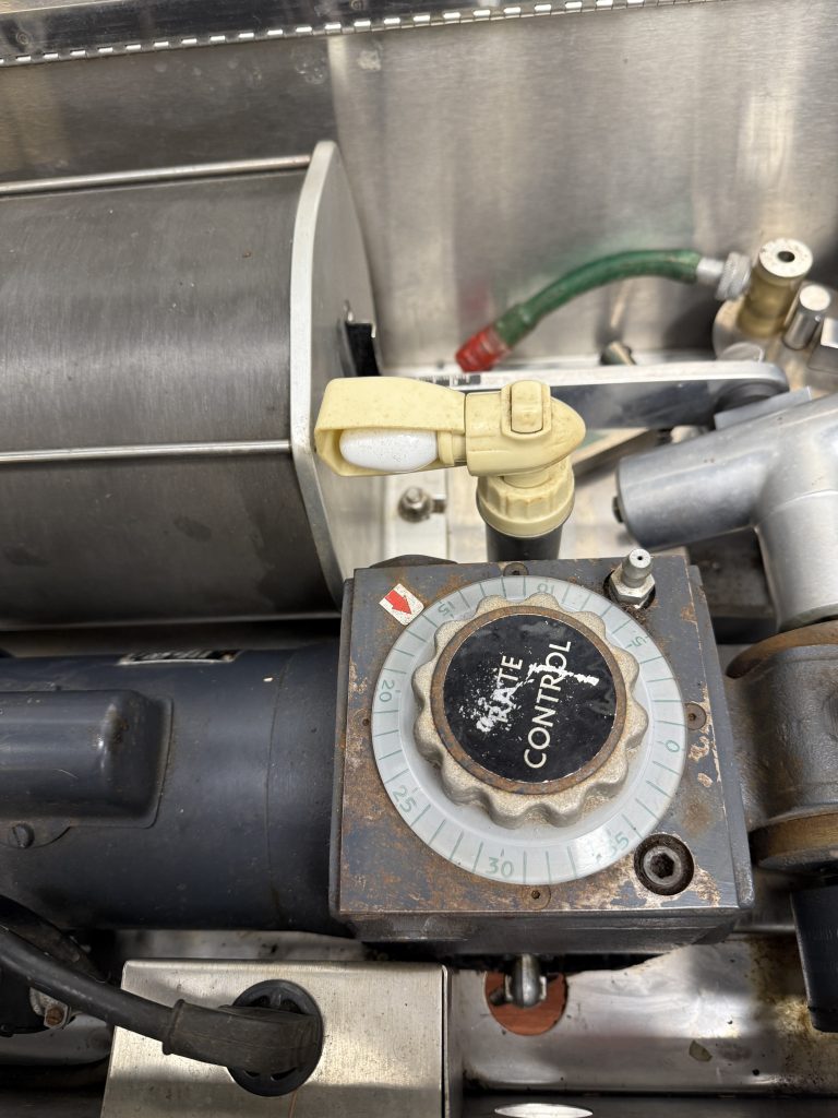
Emerson Tidal Volume Control
The crank control to adjust the tidal volume on the Emerson 3PV is shown.
Image from Felix Khusid
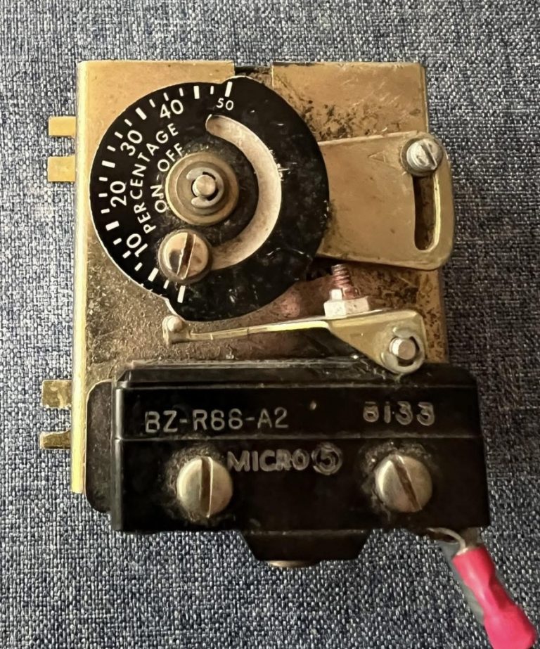

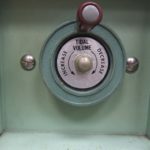
Emerson Sigh Control
This control box on the interior of the Emerson 3PV allowed the therapist to adjust the sigh volume as a percentage of the tidal volume setting or to turn the sighs off. The blower for the sigh was actually from a vacuum cleaner.
Image from Wally Smith
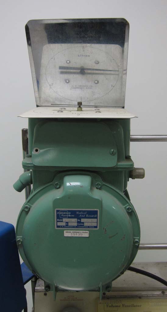
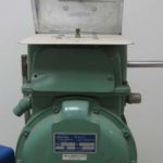
Emerson Spirometer
Emerson used a standard gas meter to monitor exhaled volumes on his ventilator. The mirror sat at an angle above the meter so one could view the movement of the indicator on the top of the gas meter which registered in 0.5 L increments between 0 and 3 L.
Image from Joseph Goss
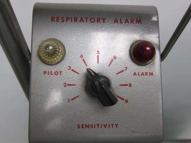
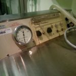
Emerson Respiratory Alarm
An auxiliary respiratory alarm for the Emerson 3PV ventilator is shown.
Image from Felix Khushid
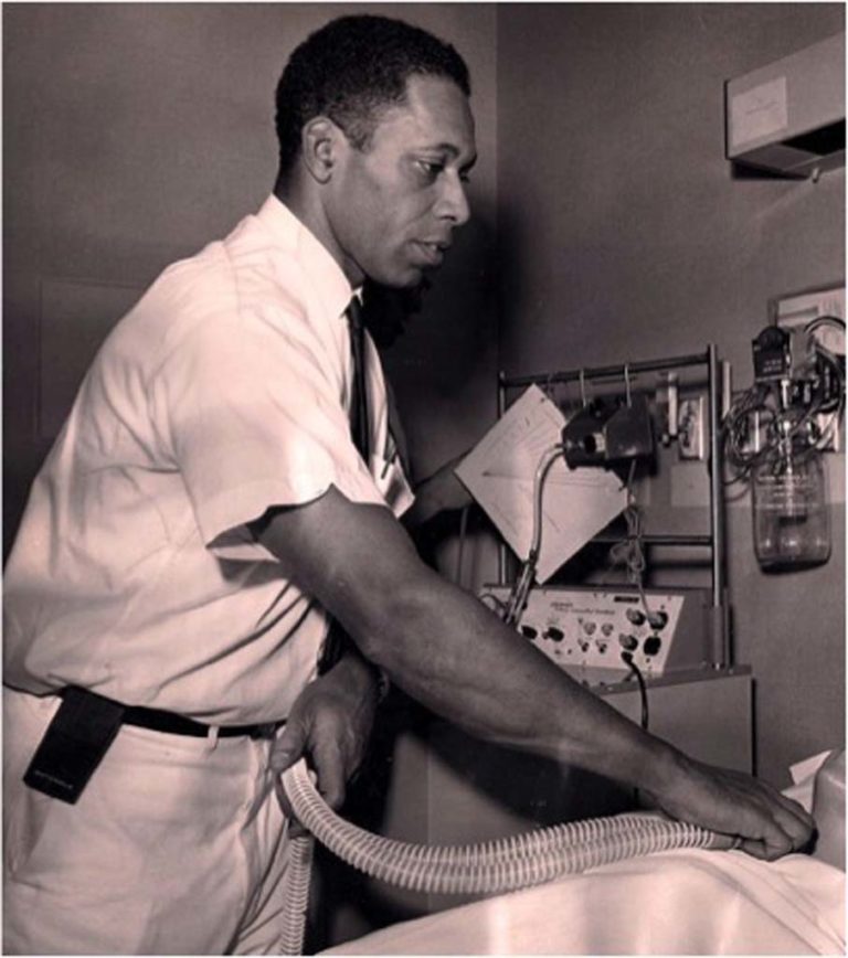
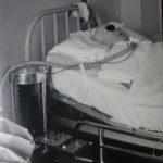
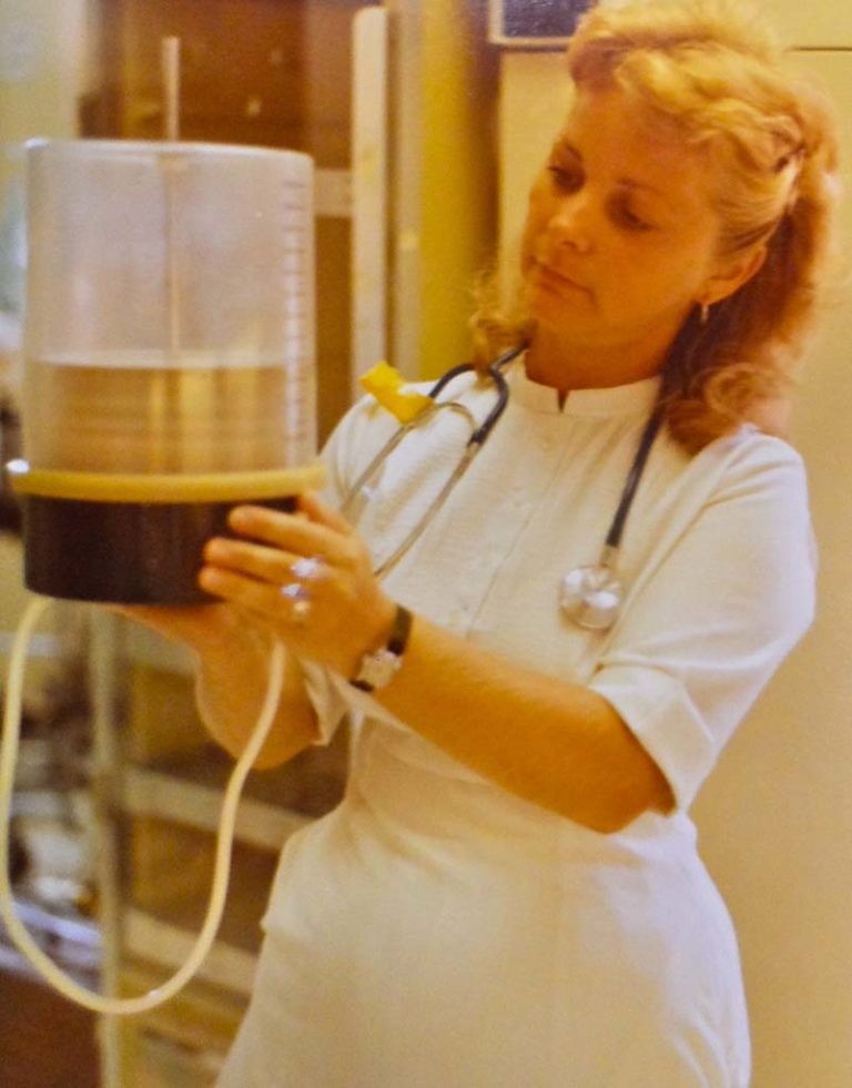
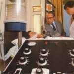
Emerson 3PV
An inhalation therapist is shown monitoring a patient on the Emerson 3PV ventilator.
Image from Steve and Mary DeGenaro
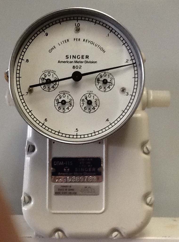
Singer Gas Meter
This Singer modified gas meter was used in conjunction with early ventilators to measure exhaled minute volume .
Image from Jeff Anderson
1967 Bennett MA-1
The Bennett MA-1 was released in 1967. The front of the unit is shown with the control panel cover in the open position.
Image from Felix Khushid
Bennett MA-1
The front of the MA-1 ventilator with the control panel cover in the closed position is shown.
Image from Joseph Goss
MA-1 Control Panel
A close up of the MA-1's control panel.
Image from Felix Khusid

Bennett MA-1 Spirometer
The Bennett Spirometer, which was used to monitor exhaled tidal volumes, is shown.
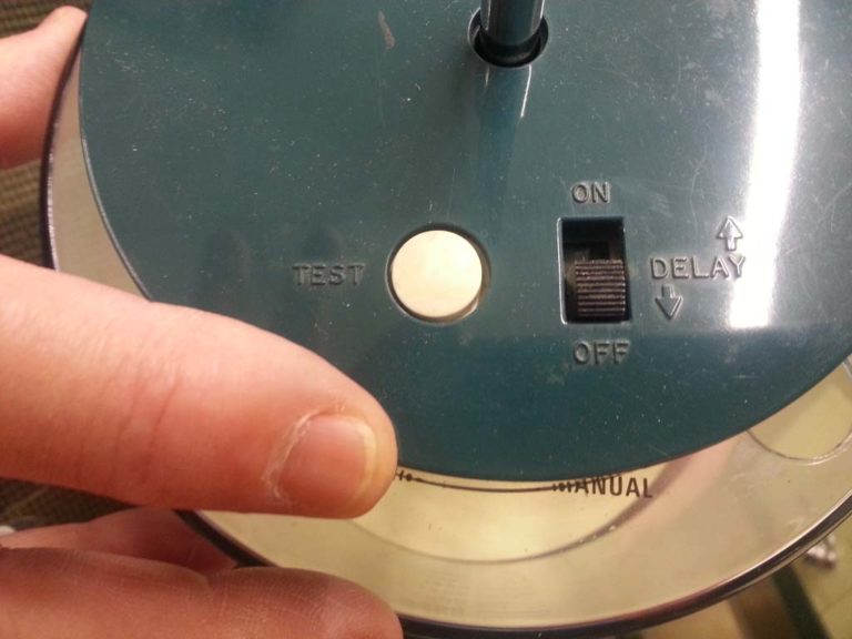
Bennett Spirometer Alarm
The Bennett Spirometer alarm had an on-off switch and a test button. The alarm volume limit was set by adjusting the "dipstick" to the desired volume.
Image from Jim Ciolek


1970s
ICU ventilators from the 1970s are featured.
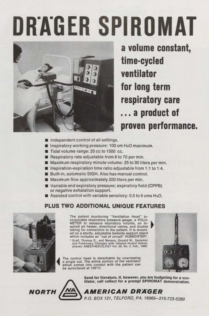
Drager Spiromat
This ad for the Drager Spiromat ventilator appeared in the February 1970 issue of the INHALATION THERAPY journal.
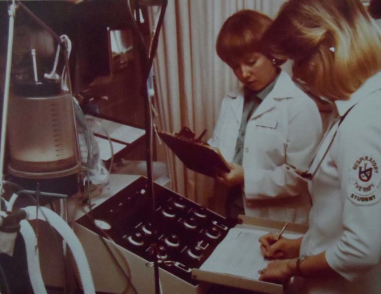
Monitoring the MA-1
As a student recorded the ventilator parameters on the patient's flowsheet, a clinical instructor monitored the student's performance.
KUMC RT Department
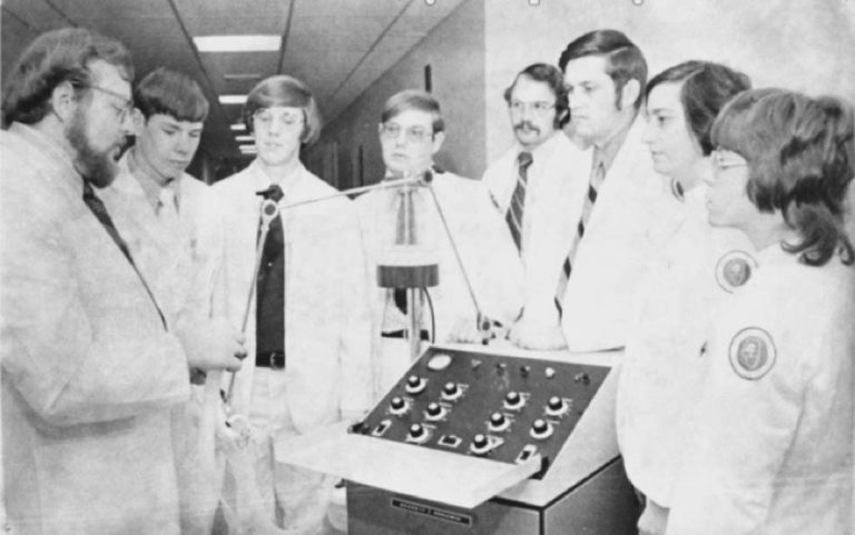
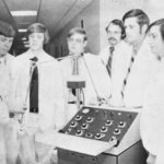
MA-1 Lab
In this 1972 photo, Gary Peschka (far left) is shown reviewing the Bennett MA-1 controls with his inhalation therapy students at Parkland College, Champaign IL.
Image from Terry DesJardins
Bennett MA-1 Circuit Change
In this photo, students are demonstrating the teamwork required during a complete ventilator circuit change.
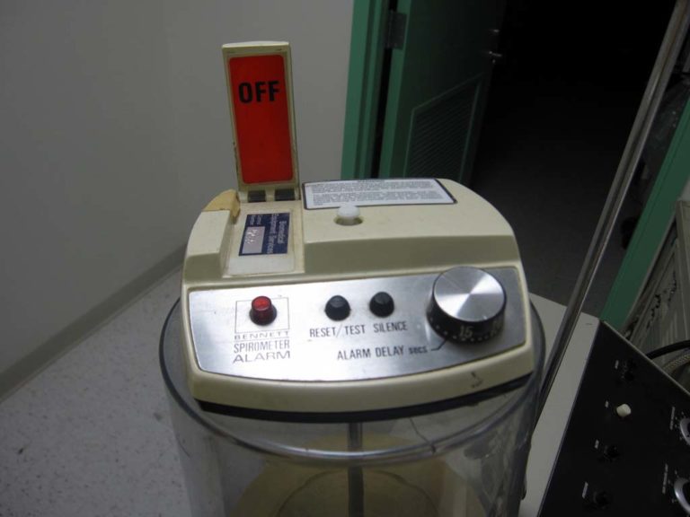
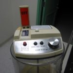
1975 Bennett SA-3 Alarm
When the spirometer alarm was turned off, a red warning flag was raised on the Bennet SA-3 Spirometer Alarm. The red "OFF" flag was a visible reminder whenever the alarm was manually turned off.
Image from Joseph Goss
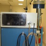
Rear view of MA-1
Circa 1975 (PEEP valve and updated spirometer alarm are present.)
Image from Joseph Goss
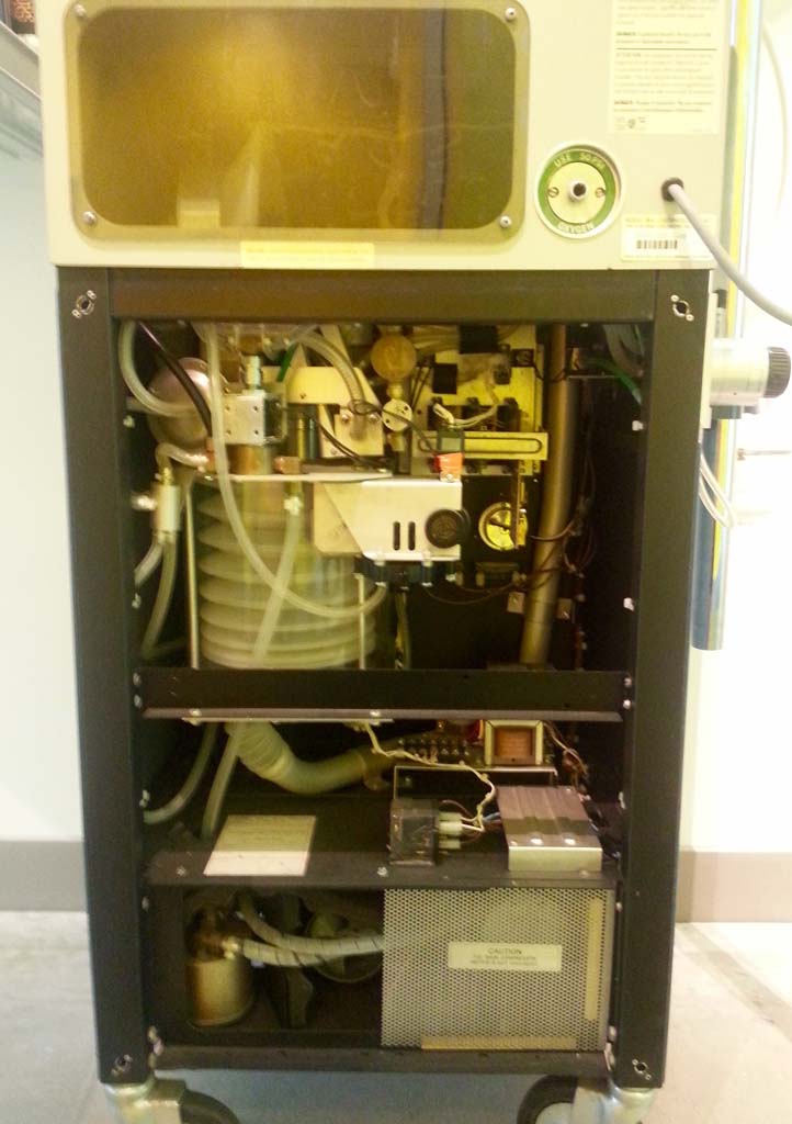
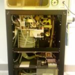
MA-1 Internal Components
With the back panel of the Bennett MA-1 removed, the internal components are visible.
Image from Jim Ciolek
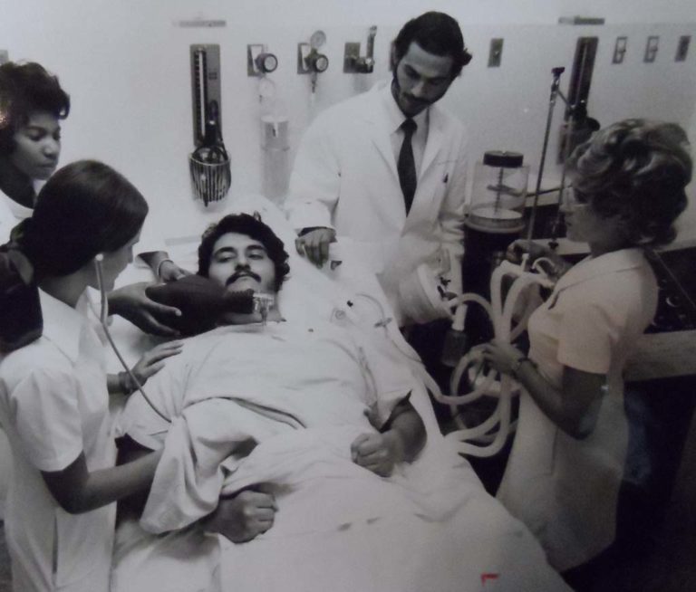
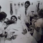
Checking a Patient on an MA-1
In this 1971 photo, Gary Jeromin is shown checking on a patient on the MA-1 ventilator,
Image from Gary Jeromin
Bennett MA-1
A clinical team monitors a patient on a MA-1 ventilator.
Image from Michael Grant

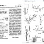
Patent Application for IMV
Jerry Liskey, RRT and Ed Story applied for a patent for "Apparatus and Method for Intermittent Mandatory Ventilation" on November 15, 1974.
Jerry initiated the development of the IMV design in 1973 while a student in the respiratory therapy program at Mt. Hood Community College. Shortly after graduation, Jerry met Ed Story in 1974 and both worked on refining the design and applied for the patent later that year.
Their patent was granted by the US Patent Office on July 6, 1976.
To view their entire patent application, enter the patent number (3967619) on the USPTO.gov website.
Image from Jerry Liskey
MA-1 with IMV and PEEP
The PEEP attachment was offered in the mid 1970s.
Intermittent mandatory ventilation was introduced in the 1970s almost a decade after the MA-1 was released. Therapists adapted the MA-1 to allow IMV through "home-made" modifications as shown here.
Intermittent mandatory ventilation was introduced in the 1970s almost a decade after the MA-1 was released. Therapists adapted the MA-1 to allow IMV through "home-made" modifications as shown here.
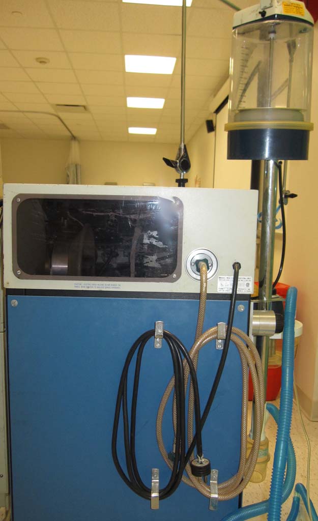
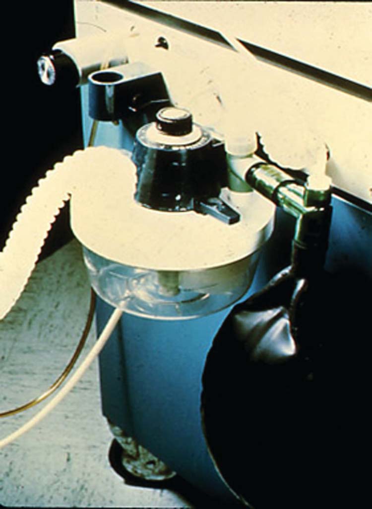
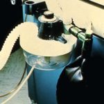
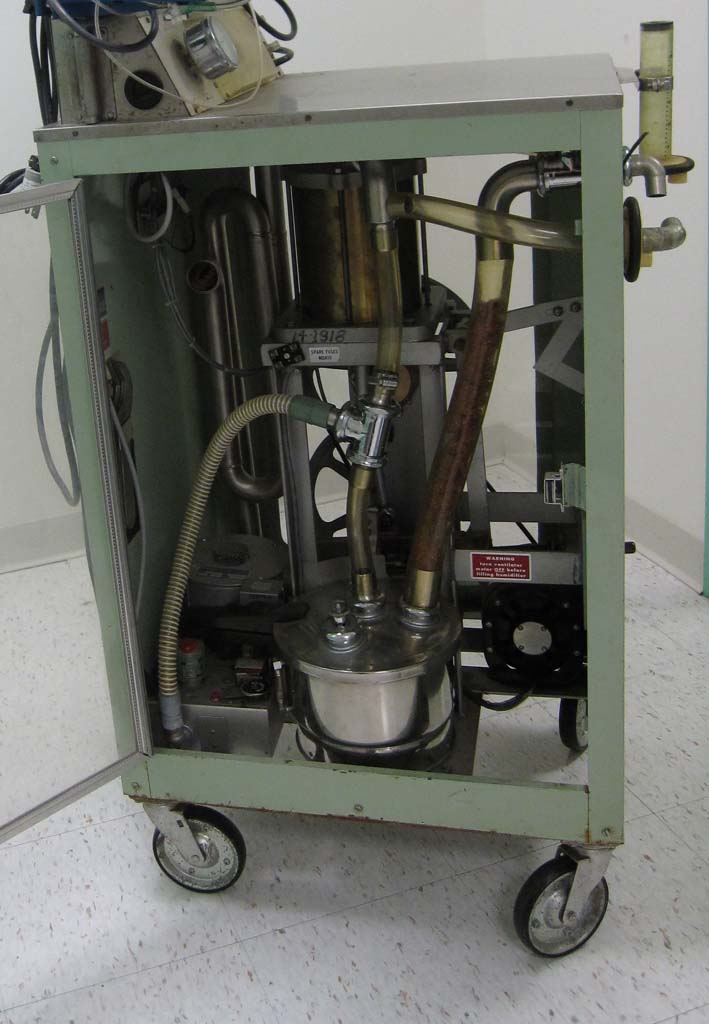
MA-1 Side with PEEP Valve
Circa 1975.
The MA-1, PEEP valve, spirometer, condensation trap and cascade humidifier are shown.
The MA-1, PEEP valve, spirometer, condensation trap and cascade humidifier are shown.
Image from Joseph Goss
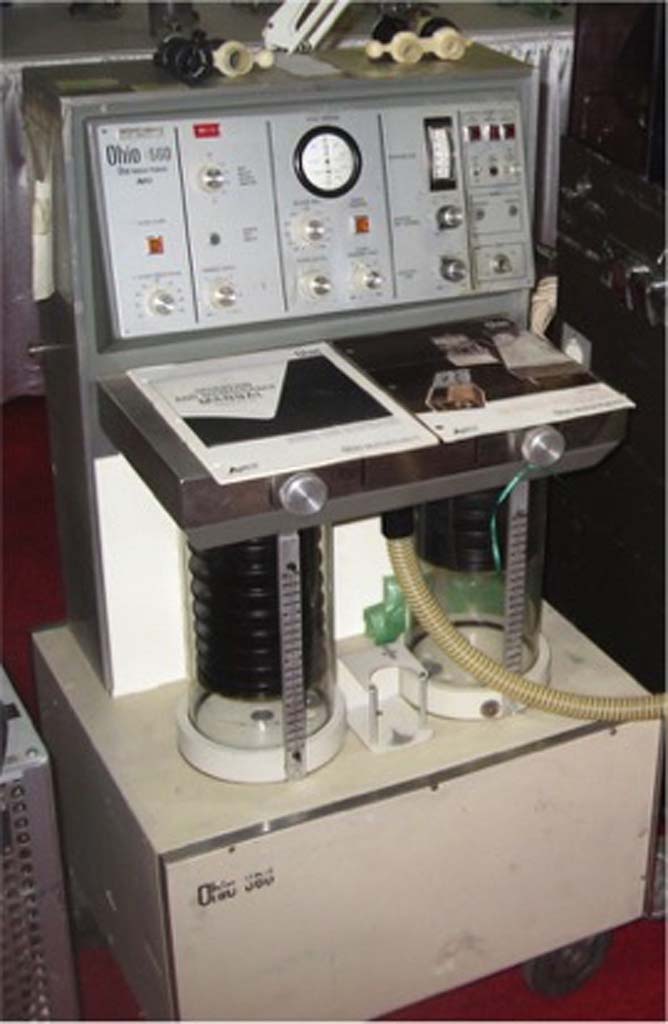
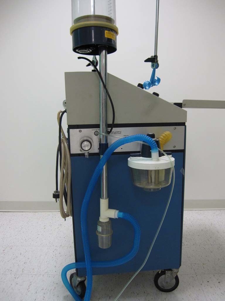
Ohio 560 Ventilator
The Ohio 560 was introduced in the 1970s.
Image from James Sullivan
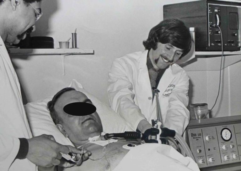
Ohio 560
The Ohio 560 is shown ventilating a patient in ICU in the early 1970s.
Image from Louis Phillip Bell-Isle
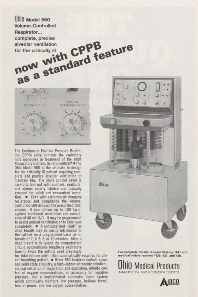
Ohio 560
The Ohio 560 Volume Controlled Respirator was featured in an ad in the December 1970 issue of the INHALATION THERAPY journal.
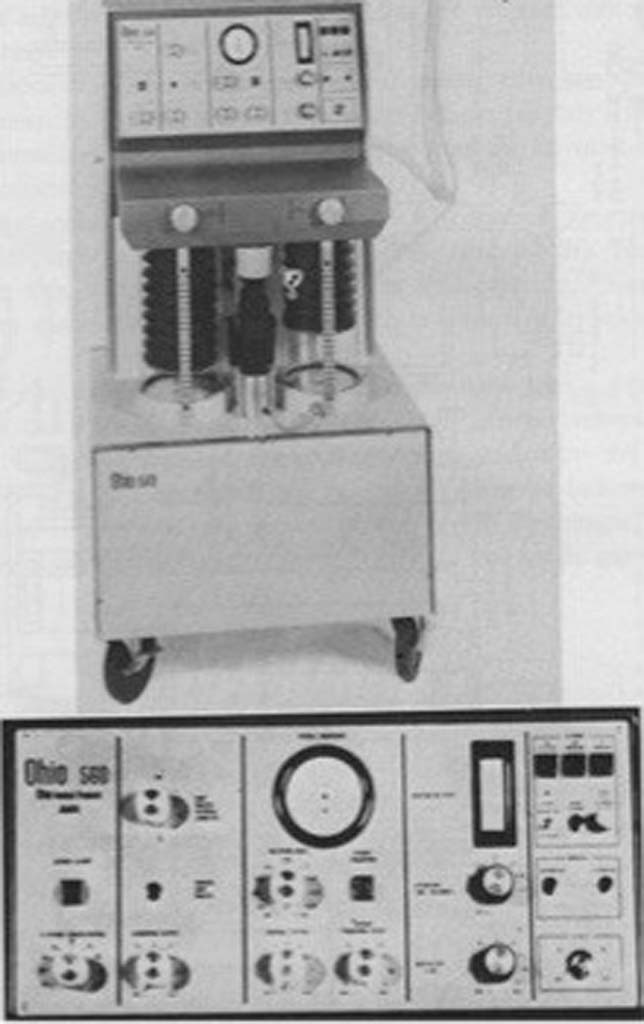
Ohio 560 Ventilator
The body and control panel of the Ohio 560 are shown.
Emerson 3PV + PEEP
The PEEP attachment, which was added to the Emerson in the mid-1970s, is shown on the top right of this image. The amount of PEEP was determined by the height to which the water reservoir on the valve was filled.
Image from Joseph Goss
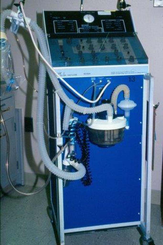
1975 Bourns BEAR
The Bourns BEAR ventilator was introduced in 1975.

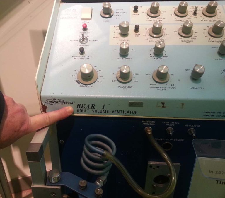
Bourns BEAR 1
The control panel of the BEAR 1 adult volume ventilator is shown.
Image from Jim Ciolek
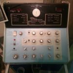
BEAR 1 Control Panel
The left front of the BEAR 1 ventilator is shown.
Image from Jim Ciolek
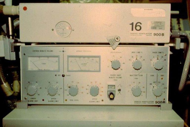
Siemens-Elema Servo 900B
Siemens-Elema introduced the Servo 900 ventilator in 1971. The Servo 900B pictured here was introduced circa 1979.
Image from Doug Pursley
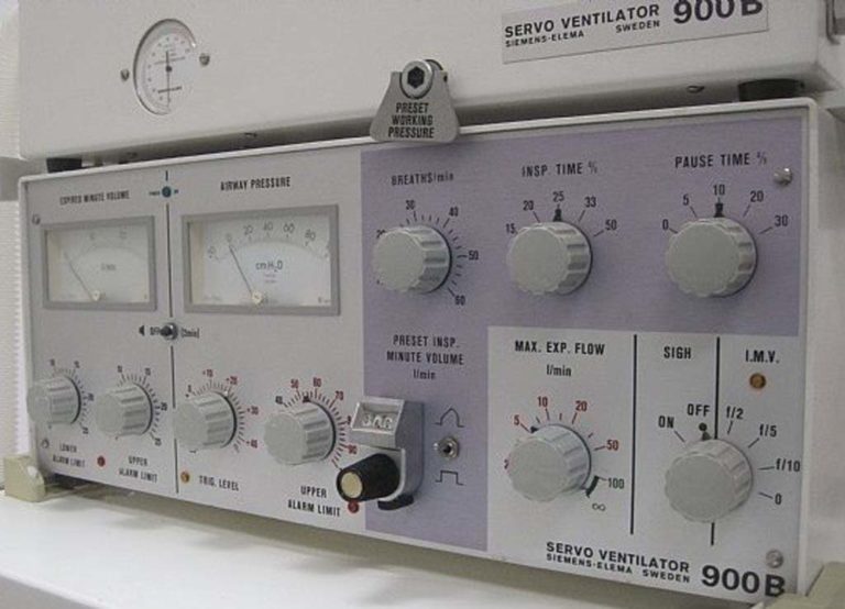
Siemens-Elema Servo 900B
The control panel of the Servo 900B is shown.
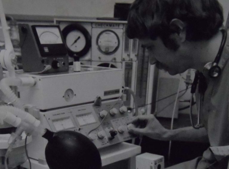
Siemens-Elema 900 B in ICU
A Siemens Servo 900 B is shown in the ICU at KUMC.
Image from KUMC Respiratory Care Program
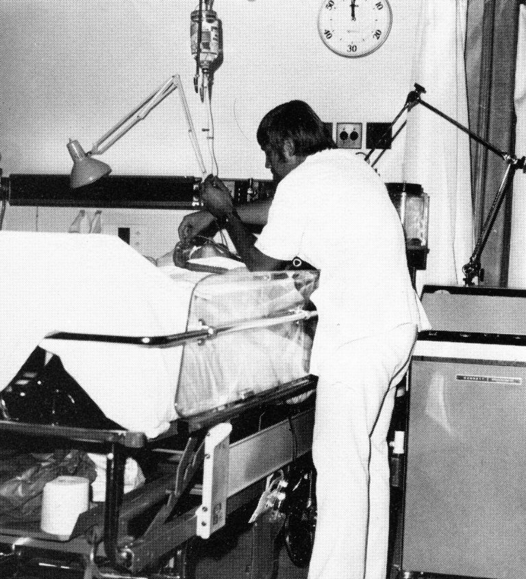
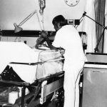
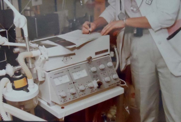
Siemens-Elema Servo 900B
A respiratory therapist prepares the Servo 900 B for use.
Image from the archives of the KUMC Respiratory Care Program
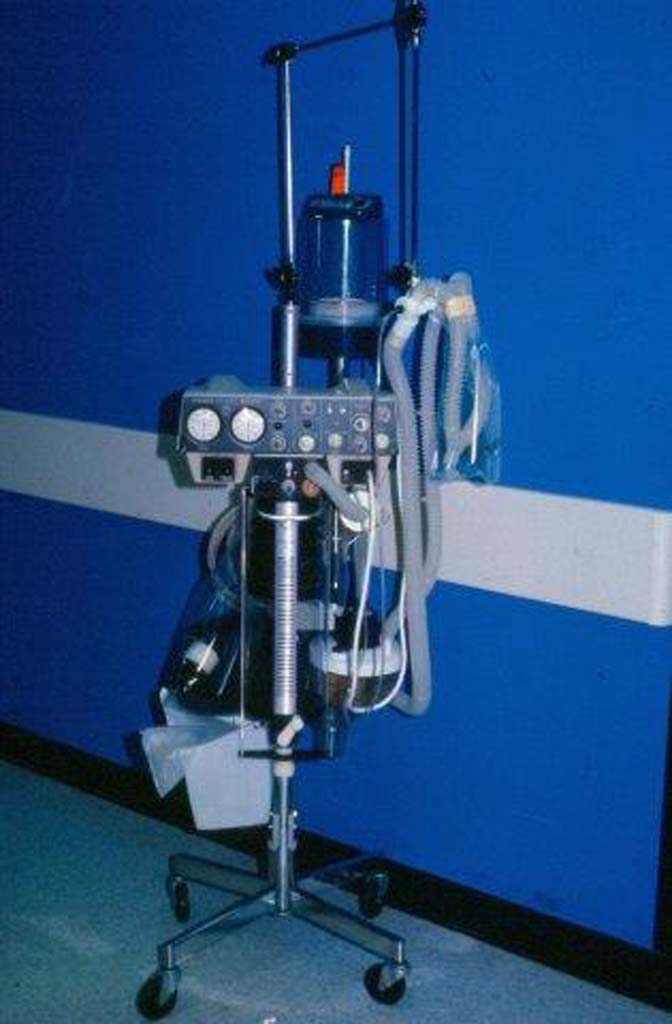
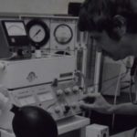
Monaghan 225
The Monaghan 225 SIMV ventilator is shown.
Image from Doug Pursley
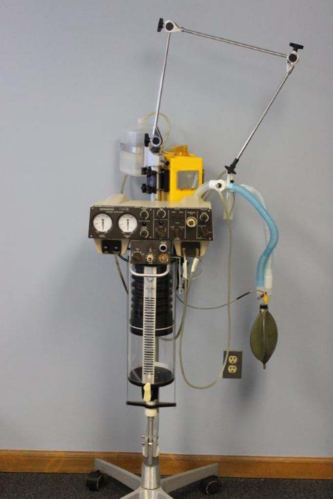
Monaghan 225
The Monaghan 225 SIMV ventilator is shown.
Image from Sheri Tooley
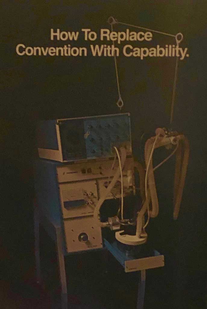
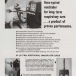
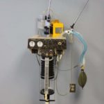
Foregger Volume Ventilator
This ad for the Foregger Volume Ventilator appeared in the January 1977 issue of RESPIRATORY CARE.
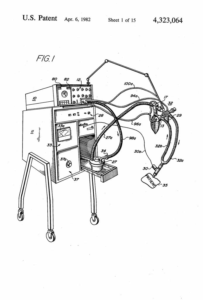
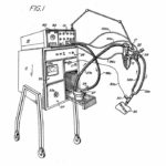
Foregger Patent Approval
Although the application was filed in 1976, the US Patent Office awarded the patent for this volume ventilator in April 1982.
United State Patent and Trademark Office
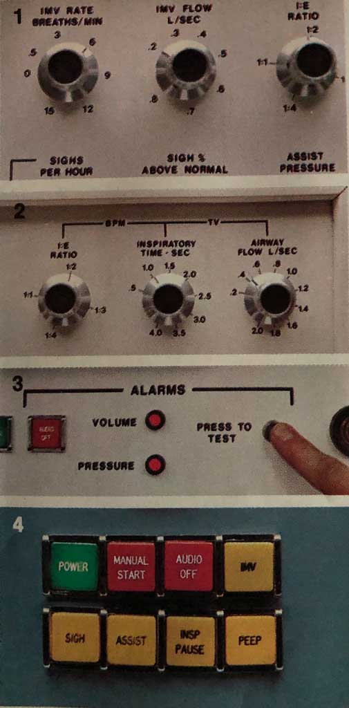
Foregger Controls
The control and alarm panels were highlighted in the ad for the Foregger Volume Ventilator that appeared in the January 1977 issue of RESPIRATORY CARE.
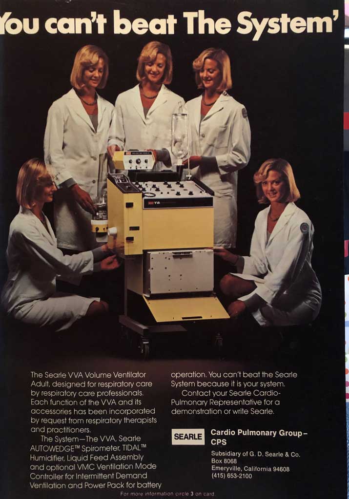
Searle VVA
This ad for the Searle VVA (Volume Ventilator Adult) appeared in the January 1977 issue of RESPIRATORY CARE.

Images to Share?
Please follow the instructions to contribute images for this gallery.